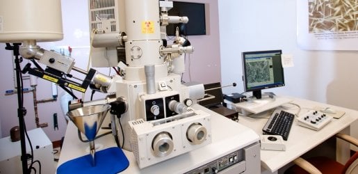
FE-SEM Internal Components

Electron gun chamber diagram

Electron Gun Chamber

Vacuum sealed chamber that contains the field emission gun. A pneumatic valve seals the gun chamber in the event of an accidental vacuum vent. This prevents dust and debris from reaching the tip.


Ion pump 1 diagram

Ion Pump 1

The upper column is maintained at a higher vacuum than the specimen chamber. The field emission tip must remain free of contaminants and oxides, requiring Ultra High Vacuum conditions (10-10 to 10-11 Torr). A normal SEM's vacuum resides around 10-5 Torr.


Electron gun diagram

Electron Gun

Source of the high voltage for the field emission gun. It is composed of the tip, two anode plates, and the gun chamber.


Field emission tip diagram

Field Emission Tip

Electron source. The field emission source for the S-4700 is a Cold Field Emission tip. This tip is made of a sharply edged piece of mono-crystalline tungsten. When sufficient voltage potential is introduced between the tip and the extraction plate, electrons are drawn off the tip at ambient temperatures, thus giving the name cold field emission.


Anode diagram

Anode

Electrons emitted from the gun are accelerated from the high negative potential of the tip to the ground potential at the anode. In the FE-SEM, a second anode is also used, placed very close to the tip. This allows for very precise accelerating voltage capacities. The combination of these two anodes determines the final electron speed down the column.


Beam monitor aperture diagram

Beam Monitor Aperture

This aperture is a passive current monitor that measures the probe current. It is used to detect current fluctuations, which are used as a reference signal to stabilize or reduce noise in the image.


First condenser lens diagram

1st Condenser Lens

The first magnetic lens that controls the beam diameter in order to produce a smaller spot size on the specimen. This lens adjusts the probe current. The smaller the condenser lens setting, the larger the probe current.


Ion pump 3 diagram

Ion Pump 3

This set of ion pump vacuums are designed to maintain the required vacuum environment inside the column.


Gun valve diagram

Gun Valve

The field emission gun (FEG) requires a better gun vacuum than a tungsten emitter. This is provided by the ion pumps. The gun valve protects and preserves the special high vacuum environment in the FEG. The valve prevents the gun chamber from venting when the vacuum has been lost in the specimen chamber.


Objective movable aperture diagram

Objective Movable Aperture

This lens has four aperture settings, one 100 μm diameter hole, two 50 μm diameter holes, and one 30 μm diameter hole. These settings influence the image resolution quality and the depth of focus. A small opening is designed to produce the highest resolution or to reduce charging on a specimen, while the larger openings are used for X-ray analysis.


Second condenser lens diagram

2nd Condenser Lens

The second set of magnetic lenses that control the probe current/probe size. In this FE-SEM, the operation mode determines whether the two condenser lenses are working separately or together.


Scan coils diagram

Scan Coils

These coils raster the beam over the sample, creating a picture pixel by pixel. The coils pull the beam off the optical axis, then return it to the optical axis by use of magnetism. Deflection coils are also used for column alignment. The image is from secondary electrons created when the beam is positioned at a point on the sample.


Objective lens diagram

Objective Lens

This unique lens focuses the beam onto the sample and helps the condenser lenses narrow the electron beam. The lens on our FE-SEM is a snorkel lens, which is specially made to project the field below the lens to mimic an ultra-high resolution "in-lens" SEM. The focus knob controls this lens.


specimen chamber diagram

Specimen Chamber

The enclosed area below the column where the specimen is located. This chamber is under vacuum! The specimen itself sits on the specimen stage, which is positioned inside the specimen chamber.


Goniometer stage diagram

Goniometer Stage

This stage face houses the knobs that control the specimen's movement within the specimen chamber. This stage is motorized in the X, Y directions and can be rotated and tilted manually.


Z axis control diagram

Z-Axis Control

Controls the specimen height from the objective lens. The space from the top of the specimen to the lens is also known as the working distance.


Rotate control diagram

Rotate Control

Rotates the specimen through 360 degrees around a vertical axis.


Tilt control diagram

Tilt Control

Tilts the specimen through a range of -5 to +45 degrees.


Y translation diagram

Y Translation

Moves the stage in the Y direction.


X translation diagram

X Translation

Moves the stage in the X direction.


Original graphics copyright Hitachi, Ltd. Adapted by Michigan Technological University.

Software