Software Introduction
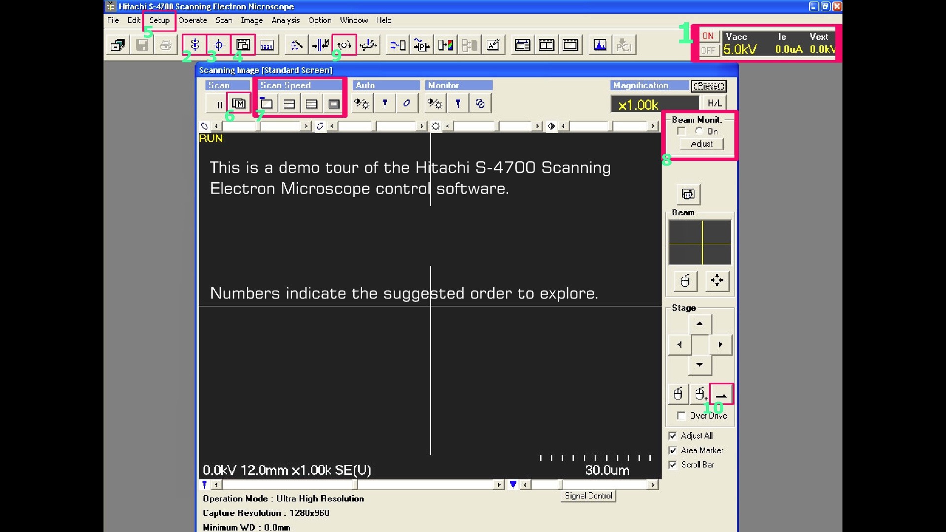
This tour of the Hitachi S-4700 Scanning Electron Microscope software features ten different control functions. Numbers indicate the suggested order to explore.
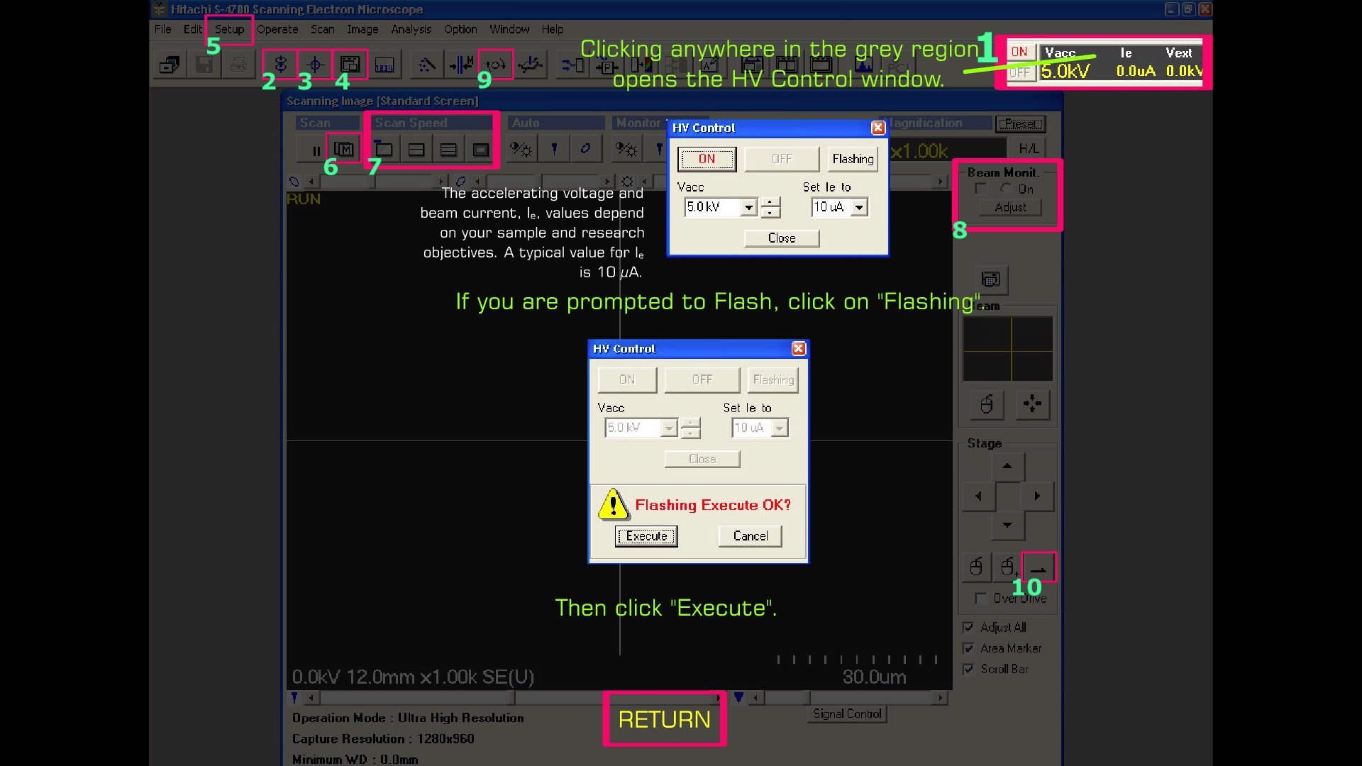
1. HV Control
Clicking anywhere on the grey region opens the HV Control window.
The accelerating voltage and beam current, Ie, values depend on your sample and research objectives. A typical value for Ie is 10 µA.
If you are prompted to Flash, click on "Flashing." Then click "Execute."
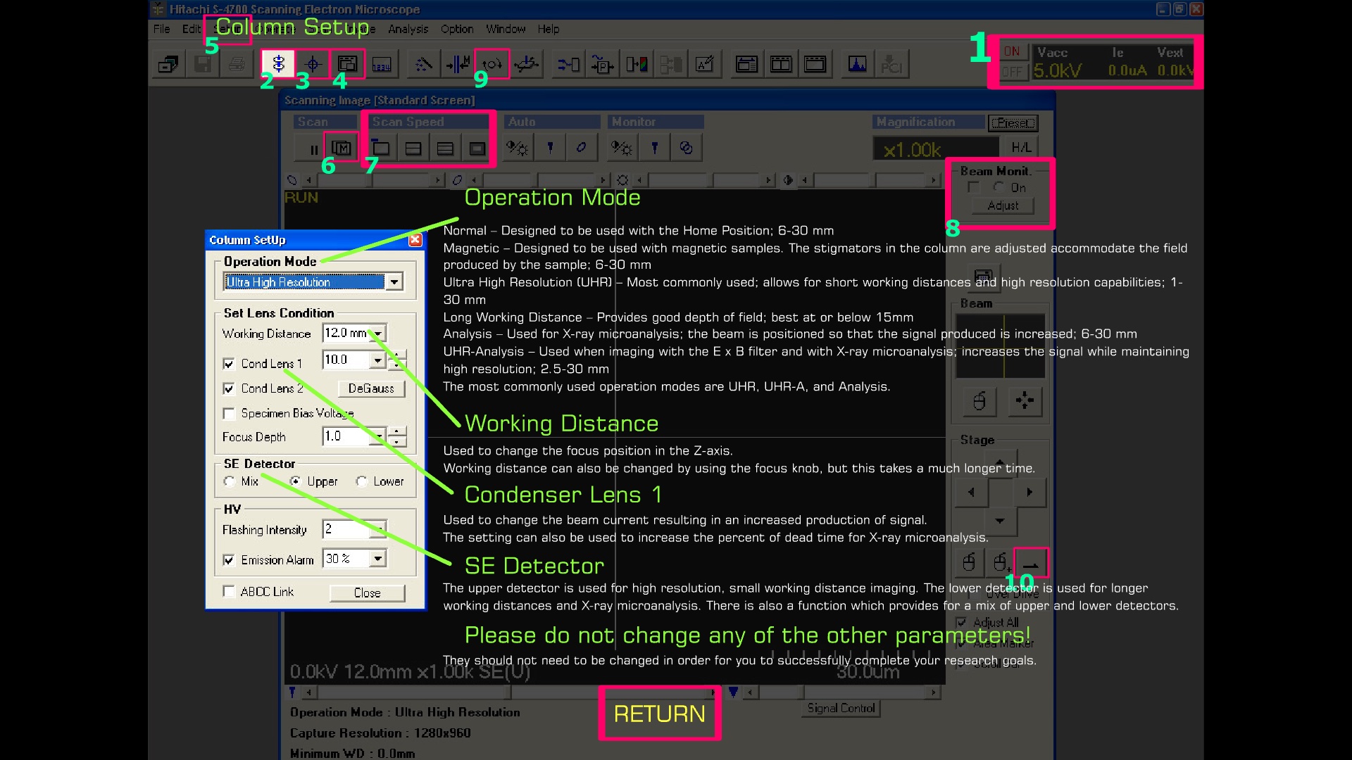
2. Column Setup
Operation Mode
- Normal - Designed to be used with the Home Position: 6–30 mm.
- Magnetic - Designed to be used with magnetic samples. The stigmators in the column are adjusted to accommodate the field produced by the sample: 6–30 mm.
- Ultra High Resolution (UHR) - Most commonly used; allows for short working distances and high resolution capabilities; 1–30 mm.
- Long Working Distance - Provides good depth of field; best at or below 15 mm.
- Analysis - Used for X-ray microanalysis; the beam is positioned so that the signal produced is increased; 6–30 mm.
- UHR-Analysis (UHR-A) - Used when imaging with the E x B filter and with X-ray microanalysis; increases the signal while maintaining high resolution; 2.5–30 mm.
- The most commonly used operation modes are UHR, UHR-A, and Analysis.
Working Distance
Used to change the focus position in the Z-axis. Working distance can also be changed by using the focus knob, but this takes a much longer time.
Condenser Lens 1
Used to change the beam current, resulting in an increased production of signal. The setting can also be used to increase the percent of dead time for X-ray microanalysis.
SE Detector
The upper detector is used for high resolution, small working distance imaging. The lower detector is used for longer working distances and X-ray microanalysis. There is also a function which provides for a mix of upper and lower detectors.
Please do not change any of the other parameters!
They should not need to be changed in order for you to successfully complete your research goals.
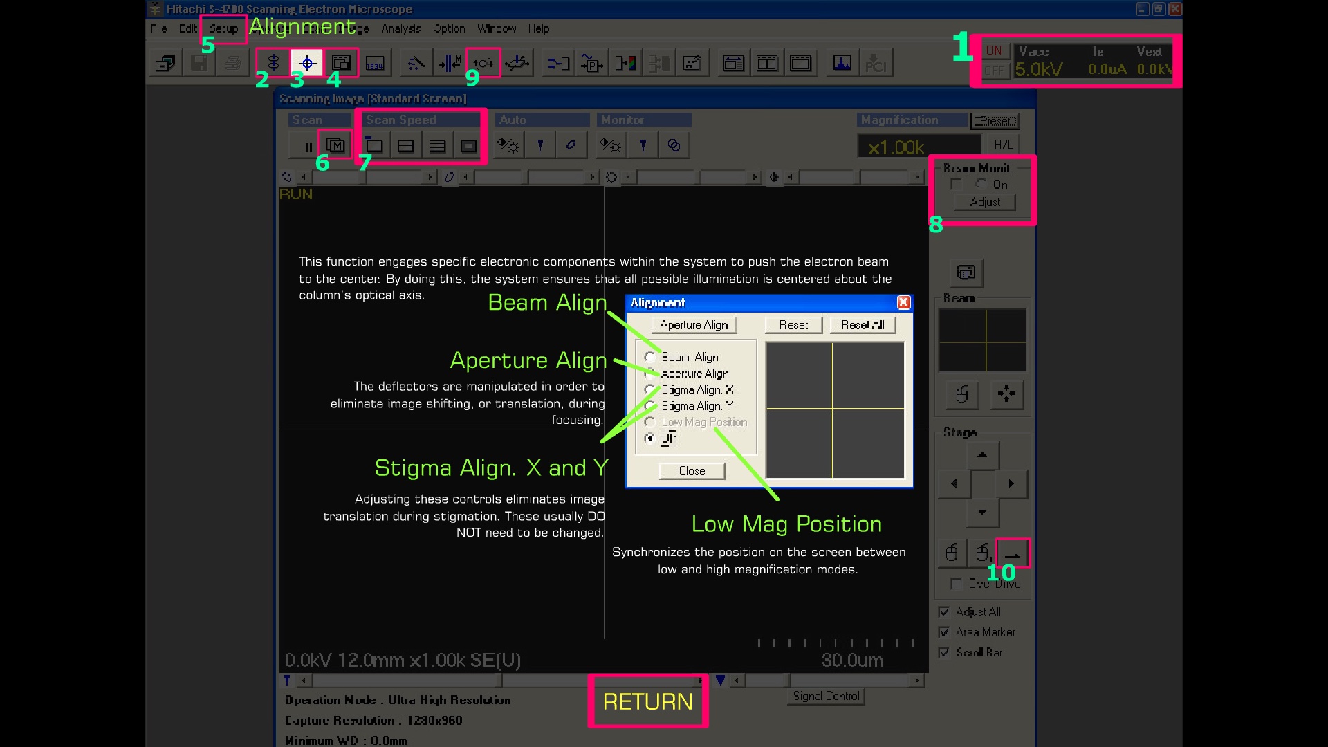
3. Alignment
Beam Align
This function engages specific electronic components within the system to push the electron beam to the center. By doing this, the system ensures that all possible illumination is centered about the column's optical axis.
Aperture Align
The deflectors are manipulated in order to eliminate image shifting, or translation, during focusing.
Stigma Align. X and Y
Adjusting these controls eliminates image translation during stigmation. These usually DO NOT need to be changed.
Low Mag Position
Synchronizes the position on the screen between low and high magnification modes.
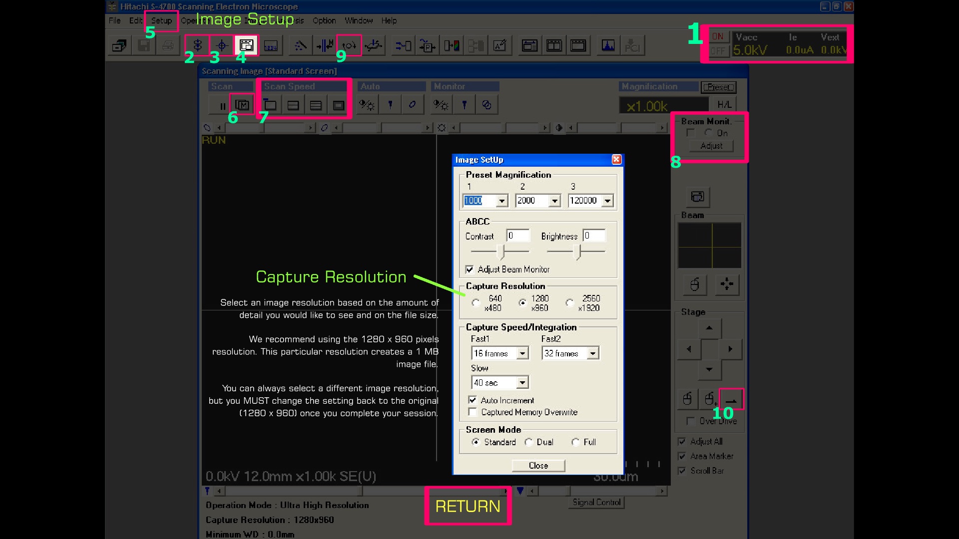
4. Image Setup
Capture Resolution
Select an image resolution based on the amount of detail you would like to see and on the file size.
We recommend using the 1280 x 960 pixels resolution. This particular resolution creates a 1 MB image file.
You can always select a different image resolution, but you MUST change the setting back to the original (1280 x 960) once you complete your session.
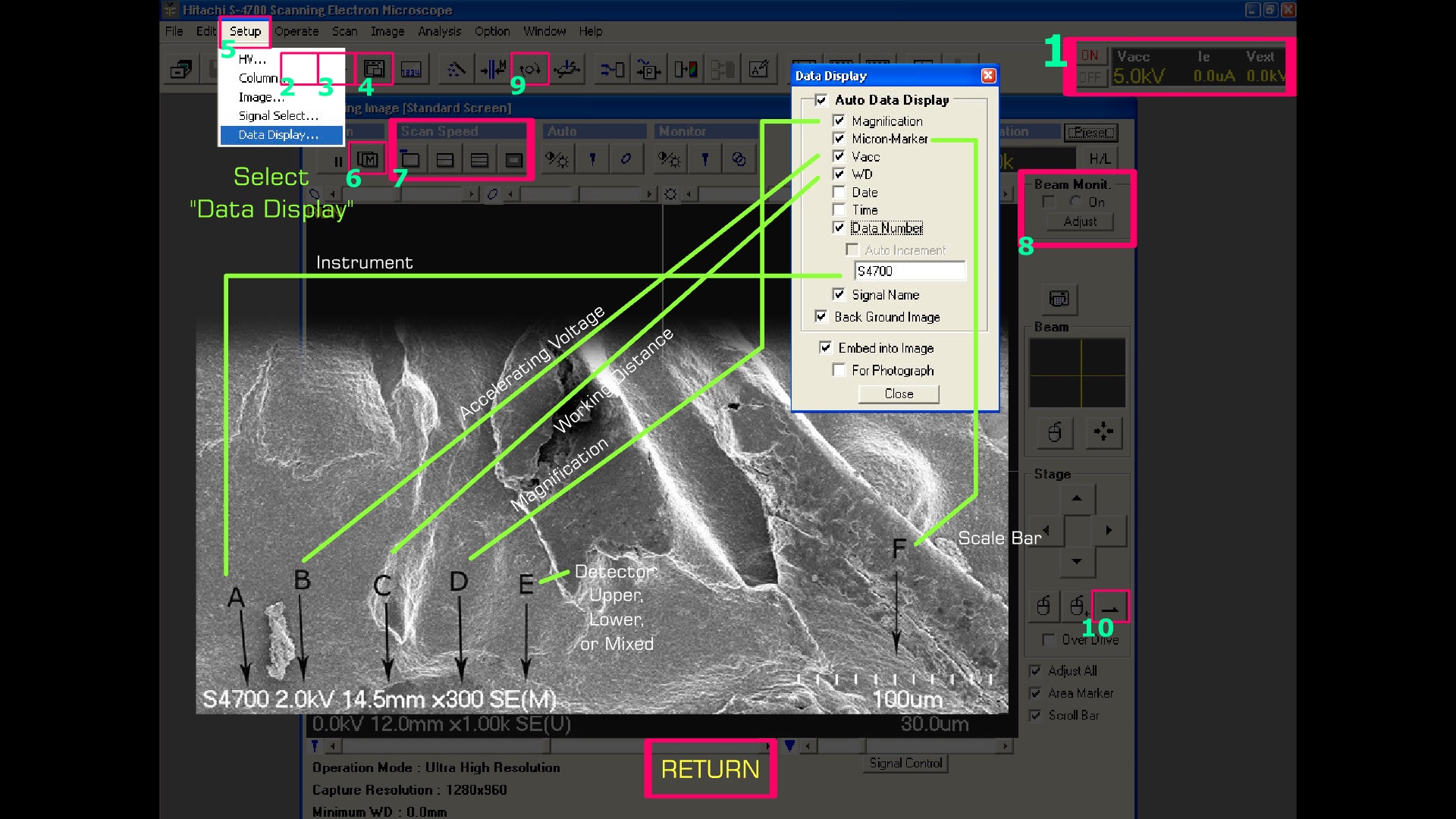
5. Data Display
Setup > Data Display . . .
- Instrument - example S4700
- Vacc - accelerating voltage example 2.0kV
- WD - working distance example 14.5 mm
- Magnification - example x300
- Detector: Upper, Lower, or Mixed - example SE(M)
- Micron-Marker - scale bar example 100 µm
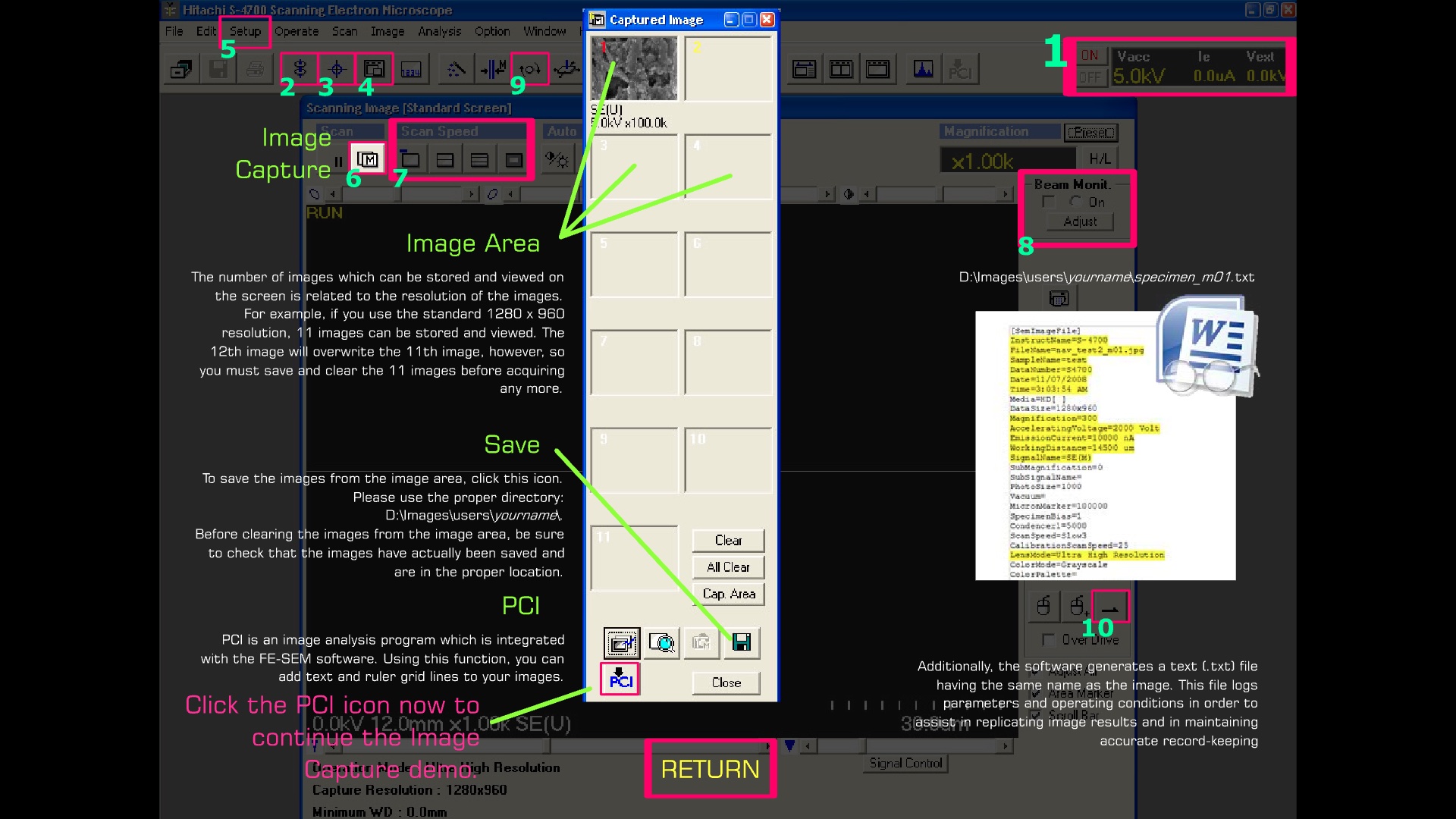
6. Image Capture
Image Area
The number of images which can be stored and viewed on the screen is related to the resolution of the images. For example, if you use the standard 1280 x 960 resolution, 11 images can be stored and viewed. The 12th images will overwrite the 11th image, however, so you must save and clear the 11 images before acquiring any more.
Save
To save the images from the image area, click the Save (diskette) icon. Please user the proper directory:
D:\Images\users\yourname\
Before clearing the images from the image area, be sure to check that the images have actually been saved and are in the proper location.
PCI
PCI is an image analysis program which is integrated with the FE-SEM software. Using this function, you can add text and ruler grid lines to your images.
Image Log
Additionally, the software generates a text (.txt) file having the same name as the image. This file logs parameters and operating conditions in order to assist in replicating image results and in maintaining accurate record-keeping.
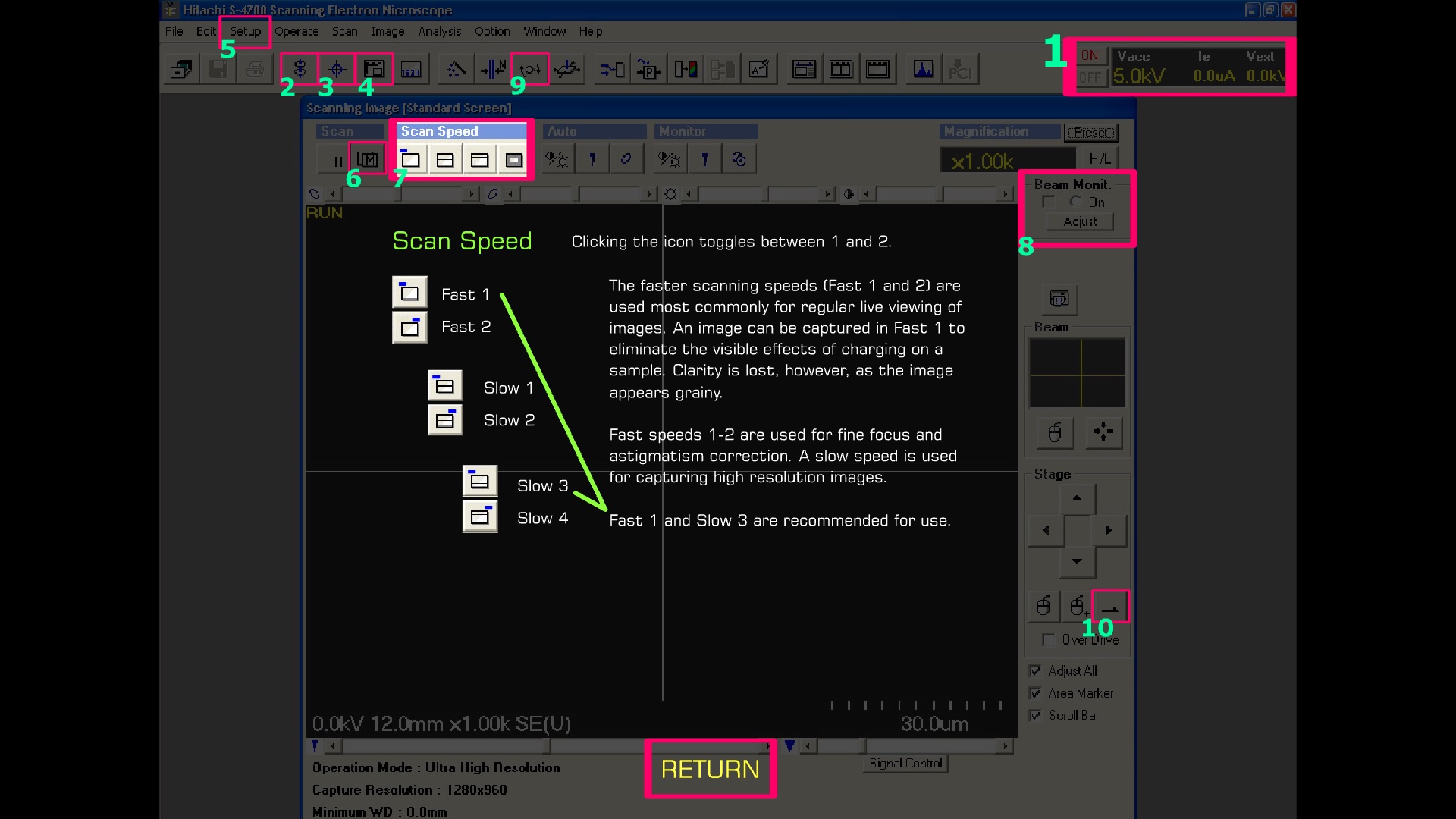
7. Scan Speed
Clicking any of the Scan Speed icons toggles between states 1 and 2.
The faster scanning speeds (Fast 1 and 2) are used most commonly for regular live viewing of images. An image can be captured in Fast 1 to eliminate the visible effects of charging on a sample. Clarity is lost, however, as the image appears grainy.
Fast speeds 1 and 2 are used for fine focus and astigmatism correction. A slow speed is used for capturing high resolution images.
Fast 1 and Slow 3 are recommended for use.
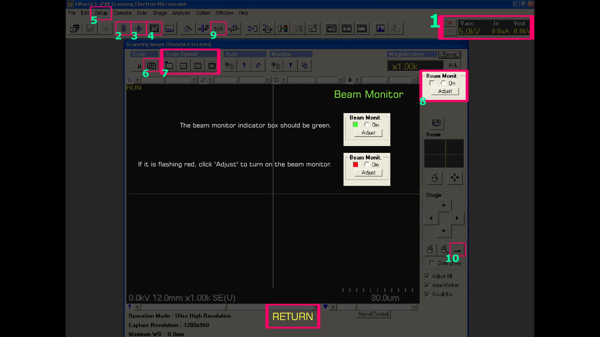
8. Beam Monitor
The Beam Monit. indicator box should be green. If it is flashing red, click "Adjust" to turn on the beam monitor.
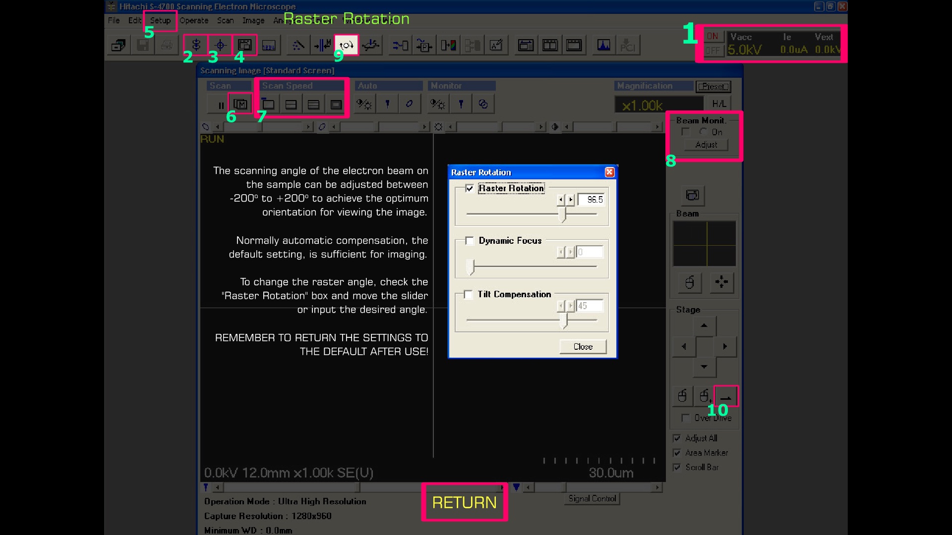
9. Raster Rotation
The scanning angle of the electron beam on the sample can be adjusted between -200° to +200° to achieve the optimum orientation for viewing the image.
Normally automatic compensation, the default setting, is sufficient for imaging.
To change the raster angle, check the "Raster Rotation" box and move the slider or input the desired angle.
REMEMBER TO RETURN THE SETTINGS TO THE DEFAULT AFTER USE!
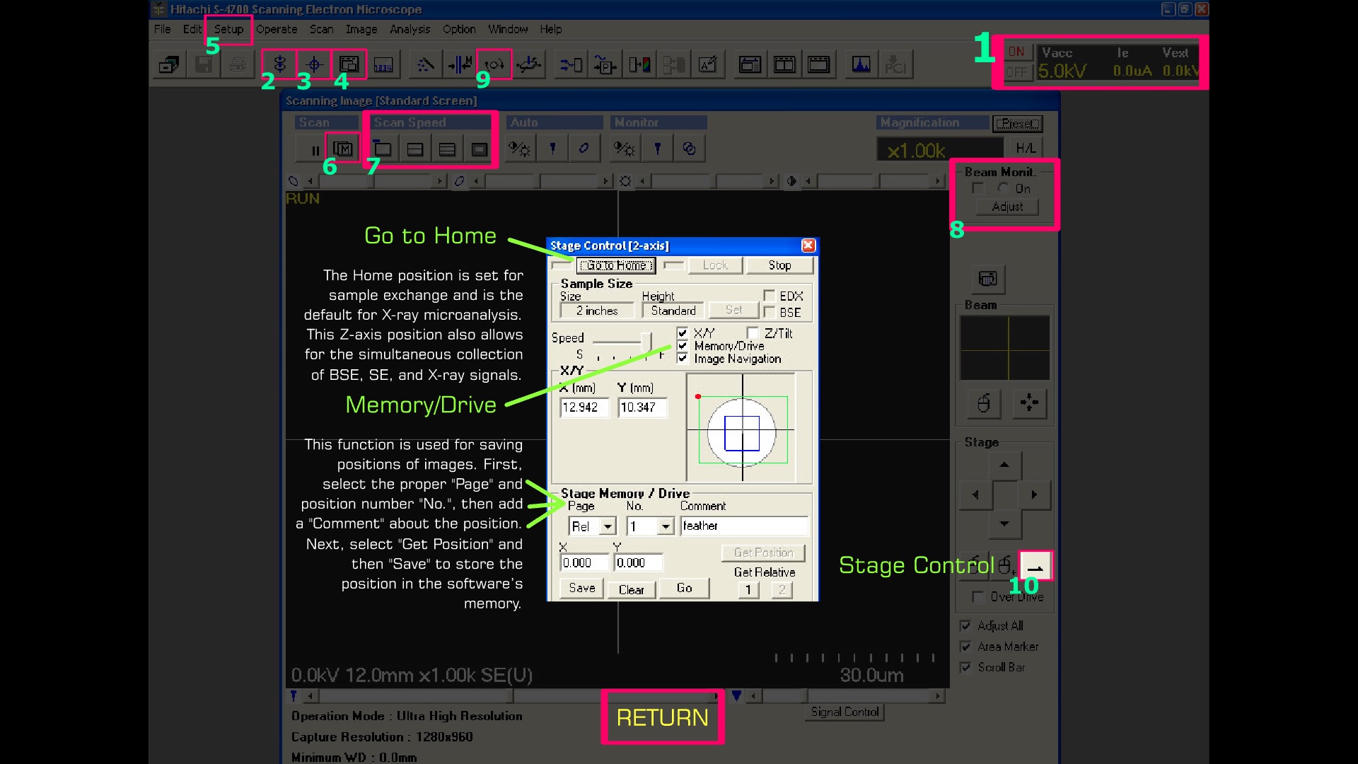
10. Stage Control
Go to Home
The Home position is set for sample exchange and is the default for X-ray microanalysis. This Z-axis position also allows for the simultaneous collection of BSE, SE, and X-ray signals.
Memory/Drive
This function is used for saving positions of images. First, select the proper "Page" and position number "No.", then add a "Comment" about the position.
Next, select "Get Position" and then "Save" to store the position in the software's memory.