Location
Minerals and Materials Engineering Building 636
Contact
Cell: 906-299-2714
Access Type
Instrument Details
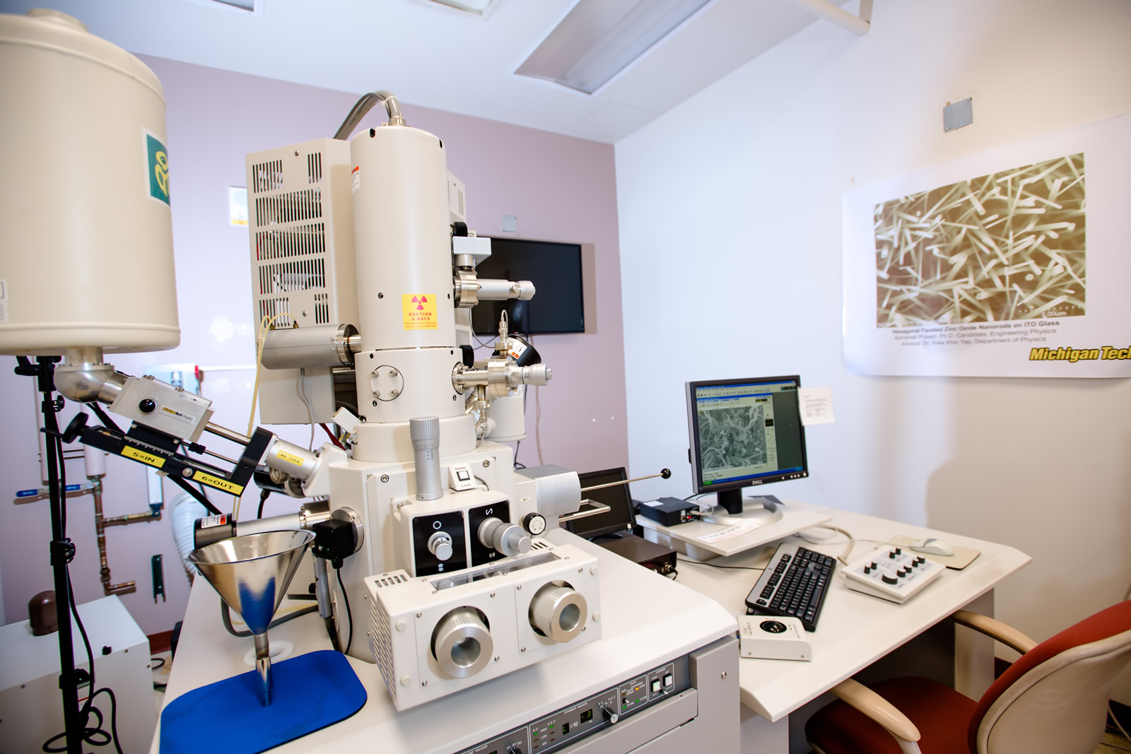
The Hitachi S-4700 FE-SEM is a cold field emission high resolution scanning electron microscope. This SEM permits ultra high resolution imaging of thin films and semi-conductor materials on exceptionally clean specimens. It is also suitable for polymeric materials. The S-4700 is configured to detect secondary and backscattered electrons as well as characteristic X-rays. The system is fully automated and is operated via easy-to-use menu driven software.
Capabilities
- Accelerating Voltages from 1–30 kV
- Everhar-Thornley secondary electron detector
- Retractable Robinson backscattered electron detector
- Through-the-lens secondary electron detector
Vendor
Hitachi
Training
eTraining
Free online eTraining is available for this instrument. This self-paced tutorial and reference content does not replace course requirements for authorized usage.