The Automation of the Cookie Cutter Manufacturing Process
Overview
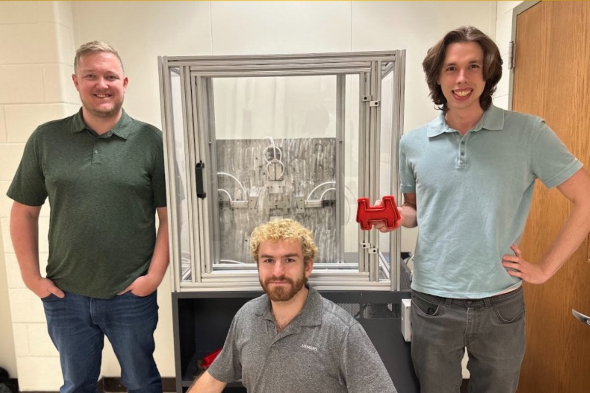
The Manufacturing and Mechanical Engineering Technology department at Michigan Technological University is requesting a redesign of the Cookie Cutter fixture. The current Cookie Cutter fixture is operated by hand pulled levers, unsafe, and is slow to manufacture a cookie cutter. Our design team is responsible for creating and implementing a new design to ensure that the new Cookie Cutter fixture is automated, safe, and has a faster production time.
In our improved design, we aimed to improve the following qualities:
- Mobility
- Ease of use
- Cycle time
- Safety
- Modular system
Fixture Redesign
The fixture was redesigned to incorporate the design constraints proved to us. Mobility was accomplished through the use of a roller cart that the rest of the unit was mounted to. Cycle time and ease of use were designed for in tandem, pneumatic actuators controlled by a PLC were implemented. We also added ejector pins to reduce the number of operations preformed by the operator. The only manual operations necessary are to load ring blanks and to press the start button. Safety was improved by building a polycarbonate enclosure with a maglock on the door. This prevents the system from running while the door is open, and restricts access while an operation is being carried out. The base plate is removable and the controller can be reprogrammed to allow other cookie cutter shapes to be used within the same housing.
Simulation
The forming process was simulated through the use of two FEA models. The top and side presses were modeled and the stress results were used to derive the force necessary to bend the brass ring blank. Our pushers were sized based off of this force and the building air supply.
Automation
To automate the cookie cutter stamper, we decided to use pneumatics for our stamping force controlled by a Programmable Logic Controller (PLC). The PLC controls five solenoid valves that power the pushers responsible for forming and ejecting the cookie cutter. The PLC is able to be programmed to power these actuators in any sequence and is reprogrammable to be used with different machine bases.
Controls
To control the machine, the operator will use three buttons. The red button is an emergency stop that turns off all power to the controls when pressed. The yellow switch is used to turn on the PLC and enable the function of the pneumatic valves. The green button starts the forming sequence. The forming sequence will stop when successfully completed or when the door of the machine is opened.
Pneumatics
Our pneumatic power for the cookie cutter stamper is sourced from a 1/2” quick connect fitting that is common with pneumatic systems. From there, we sized all of our components to use 1/4” hose with push-to-connect fittings. We added a pressure regulator to control the flow of air to our system and a lockable exhaust valve to ensure a Zero Energy State (ZES) while under maintenance.
Electrical Panel
The electrical panel is the home for all the electrical components used to operate the machine. This project used a microcontroller which is a small version of PLC. The rest of the electrical components were chosen to support the operation of the microcontroller. There are two power supplies, one to feed the pneumatic valves and one to power the microcontroller. The two circuit breakers are in the panel to prevent damage to components due to electrical anomalies.
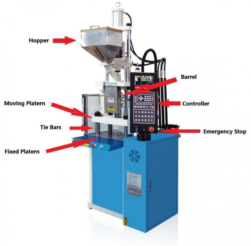
Vertical Injection Molding Machine Quick Die Change Out
Background
CEI produces overmolding for electrical plugs and adapters. The overmolding is done using the injection molding process. Currently, the molds are changed multiple times a day and the proses is completely manual from the alignment, to the mounting of the mold. CEI is looking for a way to standardize the locating and mounting of their molds to reduce cycle time and eliminate operator discretion in alignment.
Problem Statement
The current mold change process takes a total of 274 seconds. This is time when the machine cannot be operated to make a product. The main system choke is in the alignment and mounting of the mold. Currently, the operator aligns the mold by eye and mounts the die using toe clamps. With the tolerance being around .010 of an inch, it is difficult to perform correctly every time. Improper alignment or mounting could result in wasted time and operator safety concerns.
Project Objectives
The goal of this project was to greatly reduce the time it takes to change molds while improving safety, consistency, and ergonomics for the operators.
Proposed Solution
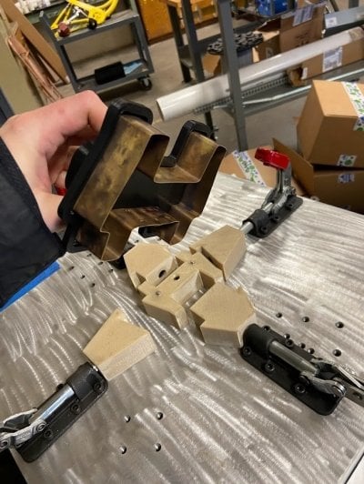
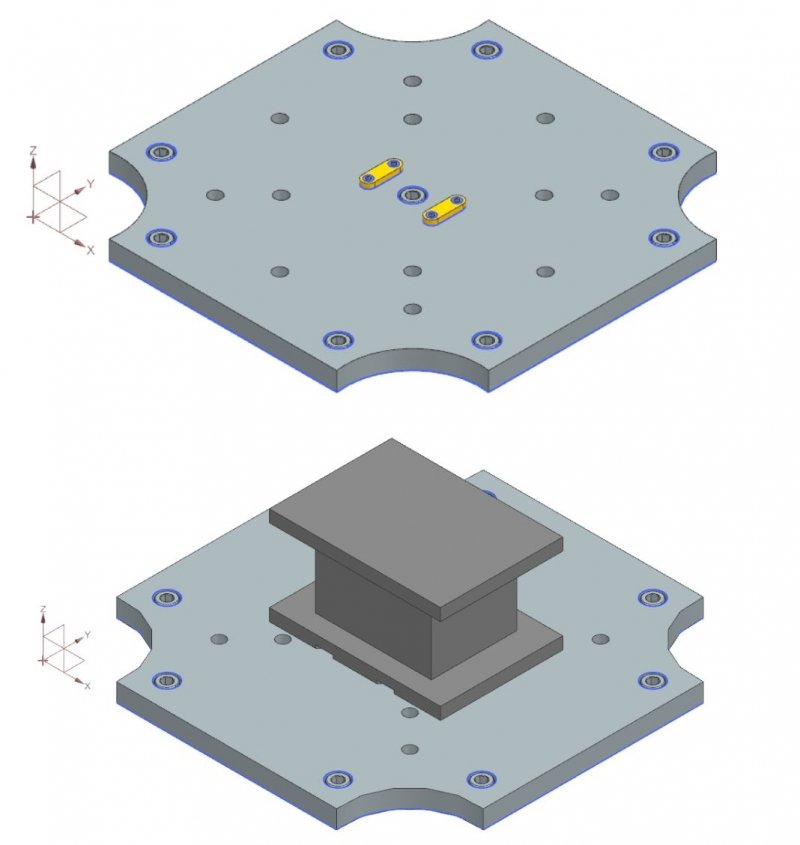
Our current solution involves creating a universal plate to be mounted to the bed of the press. This plate hosts two locating pins that engage with the bottom of the mold. This allows the mold to be slid into place while aligning the nozzle in the same motion.
Mold Modification
The plates that are already affixed to the molds can be modified using the universal alignment fixture. The fixture locates the mold upside down using the plastic injection port. This allows for precision slots to be milled in the base of the mold to interact with the alignment pins on the universal base plate.