he Energy and Thermofluids Group develops physics-based models to understand how energy is generated, converted, and transported through fluids and thermal systems. Our work is rooted in thermodynamics, fluid mechanics, and heat transfer, with applications ranging from internal combustion engines and aftertreatment systems to thermal management and HVAC systems.
We build and apply 1D and system-level models to evaluate combustion processes, diesel aftertreatment performance including DOC, CPF, and SCR systems, and integrated thermal management architectures.
Our simulation tools include MATLAB and Simulink, GT-SUITE and GT-POWER, Simcenter Amesim, AVL CRUISE M, KULI for thermal systems, and Argonne’s GREET and Autonomie. In addition to commercial software, we develop custom models to address specific research questions where detailed physics representation is required.
These modeling capabilities support research, guide experimental design, and provide quantitative insight into complex energy and thermofluid systems.
Computational Fluid Dynamics (CFD)
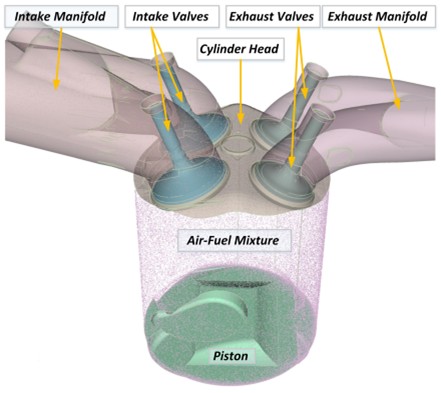
Computational Fluid Dynamics (CFD) is a tool commonly used at the APS LABS for high-fidelity system optimization to help provide insight into in-cylinder combustion providing problems such as flow field factors and pressure distributions well in advance of prototype validation. We are well versed with CONVERGE, which is the industry standard for combustion CFD, as well as Ansys Fluent.
The example below shows an open cycle CFD model of an RCCI engine in CONVERGE.
The CFD model was used to determine relative reactivity index (RRI) distribution at different operating conditions of the engine, as shown below.
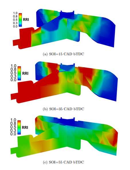
Relative Reactivity Index (RRI) distribution at PR=20, FQ=4 mg/cycle, and (a) SOI=15°bTDC, (b) SOI=35°bTDC, (c) SOI=55°bTDC
Another application of CFD in Ansys Fluent is cold flow analysis of the exhaust port of an engine project to determine the magnitude and locations of possible improvements as well as how the proposed port design may interact with downstream components. Modeling this in a 3-dimensional environment showed large sensitivity to valve guide shape and internal bend radius that wasn’t captured in 1D analysis. 3D CFD shows flow separation forming a dead zone, effectively reducing the cross-sectional area of the port.
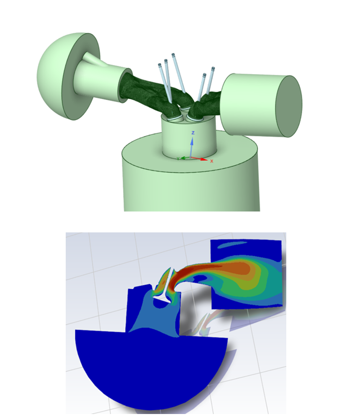
The modeled port shape also indicated a great sensitivity to flow matching on the exhaust manifold near the top, where the high flow velocities can easily be disrupted by either gasket or manifold matching inconsistencies. More than just exhaust ports, APS LABS is able to apply this level of analysis to solve problems like intake manifold flow distribution, cooling, and fuel injection. This level of insight allows us to move into the test cell, knowing that all possible performance is on the table.